Email Us

Analog Galvo Driver

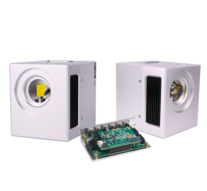
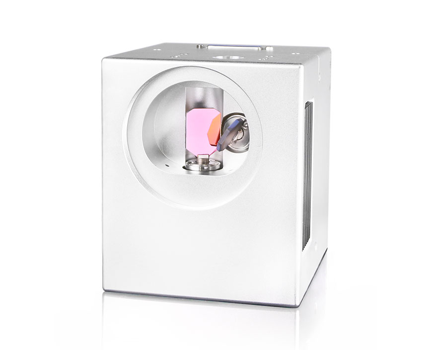
Han's Scanner analog galvo driver board is designed for the full series of Han's Scanner photoelectric galvanometer motor, using the traditional PID closed-loop control mode, stable and reliable performance;  with a variety of different configurations, support analog and digital signal input, a variety of different power amplifier devices can drive mirrors  with different loads from 3mm-50mm to achieve optimal dynamic performance, to meet the speed and accuracy requirements of various high-end applications. 

GET A QUOTE
Galvanometer Mirror Scanner
Galvanometer Scanning Mirror
Galvo Mirror Scanner

Key Features Of Analog Galvo Driver


  • 3-in-1 analog driver board


  • Integrate DA card and analog driver board, compact size


  • TDA8950 D class work output, low heat


  • First generation galvo driver


  • More than 10 years in the market, stable performance


  • A driver board drives a galvanometer


  • LM3886 AB dual-power amplifier, maximum 68W+68W power output, strong driving capability


  • Second generation analog driver board


  • TDA8950 type D power amplifier output, low heat


  • A driver board drives a galvanometer, driving capacity is strong


  • TDA8950 power amplifier, maximum 150W+150W power output, strong driving ability


Improved speed performance by more than 50% compared to the first generation analog driver board.

Download
  • Analog Drive Manual 2
  • Analog Drive Manual 1
Leave a Message
*
*
*
*
*

Specifications Of Analog Galvo Driver


Analog Galvo Driver Electric Parameter


Power Supply Requirements

+/-15 to +/-28 VDC Configurations Available

Maximum Drive Current Limit

10 AMPS Peak

5 AMPS Rms (Power Supply And Load Dependent)

Operating Temperature Range

0~50℃


Analog Galvo Driver Interface Definition


Galvo Motor System


Connector Definition


Description

J2 (10pin) Of Driver ST16xx

GND

1

GND

2

GND

3

GND

4

POS1

5

MOTOR+

6

MOTOR-

7

GND

8

LED+

9

POS2

10


Description

J1 (2pin) Of Driver ST16xx

-

1

+

2


Description

J3 (4pin) Of Driver ST16xx

-15V

3

GND

2

+15V

4

NC

1


Description

J4 (10pin) Of Driver ST16xx

NC

1

POS_FB

2

GND

3

CMD_ERR

4

V_CRT

5

V_LED

6

NC

7

NC

8


1. Electronic Parameters


Power Supply Requirements

+/-15 to +/-28 VDC Configurations Available

Maximum Drive Current Limit

10 AMPS Peak

5 AMPS Rms (Power Supply And Load Dependent)

Operating Temperature Range

0~50℃


2. lnterface Definitions


Galvanometer Scanning Mirror


Connector Definition


Description

J2 (10pin) Of Driver Board ST16XX

Remark

GND

1

Power Ground

GND

2

Power Ground

GND

3

Power Ground

GND

4

Power Ground

POS1

5

Photocell Position Feedback Signal 1

MOTOR+

6

Motor Signal +

MOTOR-

7

Motor Signal -

GND

8

Power Ground

LED+

9

LED Positive Terminal

POS2

10

Photocell Position Feedback Signal 2


J1 Analog signal control port, communication through serial port


Description

J1 (2pin) Of Driver Board ST16XX

Remark

-

1

Analog Negative Signal Input (Pulse Signal)

+

2

Analog Positive Signal Input (Pulse Signal)


Description

J3 (4pin) Of Driver ST16xx

Remark

-15V

3

Negative Of Power Supply (Current 3A)

GND

2

Power Ground

+15V

4

Power Supply Positive Electrode (Current 3A)

NC

1

Suspend In Midair


Description

J4 (10pin) Of Driver Board ST16XX

Remark

NC

1

Suspend In Midair

POS_FB

2

Motor Position Feedback Signal

GND

3

Power Ground

CMD_ERR

4

Command Error

V_CRT

5

Motor Current Sampling Signal

V_LED

6

Motor LED Voltage

NC

7

Suspend In Midair

NC

8

Suspend In Midair


Galvanometer Application

Please Contact Us!
TO KNOW MORE ABOUT HAN'S SCANNER PRODUCTS
Related Galvo Scanner
Global Leader Of Optical Scanning System Solutions
To Find More

4F Building4, Han's Laser Industry Park, 128 Chongqing Street, Fuyong, Bao'an District, Shenzhen City, Guang Dong, P.R. China.

US office address:4224 clay business Dr.,Katy,TX 77449,US
scanner@hanslaser.com +86 0755-27333701